
First of all here you have sim800 hardware design and here the AT commands.
SIM800L is a quad-band GSM/GPRS module that works on frequencies GSM 850MHz, EGSM900MHz, DCS1800MHz and PCS1900MHz. SIM800L features GPRS multi-slot class12/ class 10(optional) and supports the GPRS coding schemes CS-1, CS-2, CS-2, CS-3 and CS-4.
The power supply for 800L is between 3.4V and 4.4V but the module in the pictures below has a voltage regulator which allow to power it from arduino (but someone on youtube told me that this module could consume up to 2A in a burst mode and this is true 🙂 , so, if your module doesn’t work, you can connect it to a 5Vdc power supply, but don’t forget to make common GND with arduino, for me worked perfect direct from arduino)


As you can see the module have 7 pins as:
5V-you can connect to the arduino 5V
GND-to arduino GND
VDD-not used
SIM-TXD-to a arduino PWM pin
SIM-RXD-to a arduino PWM pin
GND-to arduino GND
RST-not used
To start you have to connect pins like above, I choose SIM-TXD to pin 10 and SIM-RXD to pin 9.
For a period of time, let’s say 1 minute it tries to connect at the mobile network and the NET led will blink at 1 second period and after it connects to the network the LED will blink at 3 seconds.
From this moment it is ready to go.
To make the module to communicate with arduino you need to use the softwareserial library(it is in arduino software) and choose the pins you want to use(in our case is about 9 and 10 ). After that we must set the baud rate for the module(we choose 9600) and for the serial monitor(also 9600) because we make the program to receive message too and display the message received on serial monitor.
In the program we have two functions, one to send message and one to receive message. Because we want to have a practical use the message will be sent, or received after one button connected to digital pin 12 is pressed.
Before to receive message you must send one, after that you must comment “//” the sendmessage() and enable(without “//”) receivemessage(), upload it , open the serial monitor, push the button
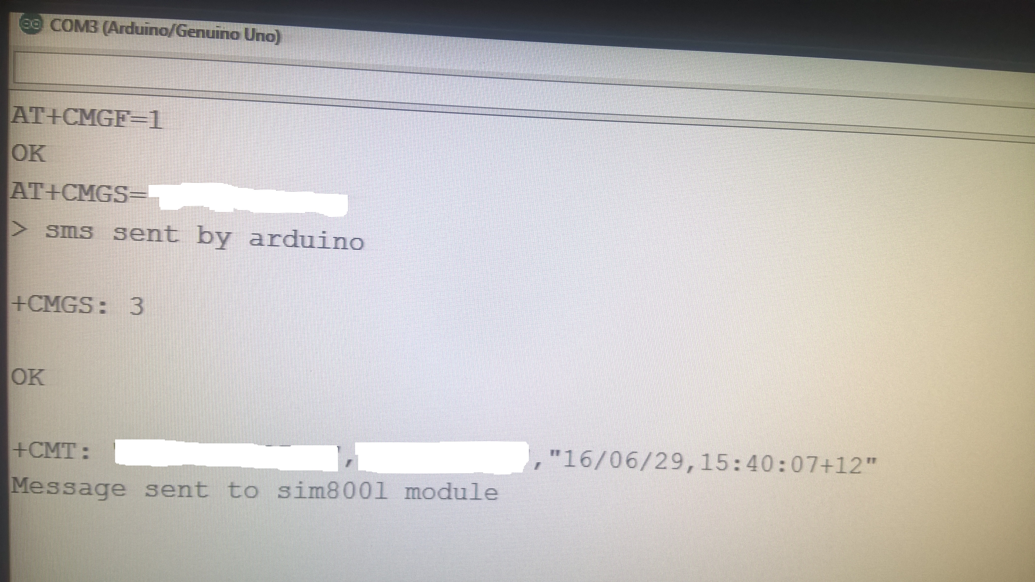
and you must see A+CNMI=2,2,0,0,0 and OK. Now you can receive messages. If you enable the sendmessage() and comment receivemessage() and upload it you can send message by pushing the button and in the same time receive messages like in the picture below(we have sent a message and received a message).
This program you can download from here.
So if you have a sensor which when it is enabled or if you just want to send a message with a button now you can.
But what if we have multiple sensors or buttons. For that we have made a program which can be downloaded from here.
In this program are 2 functions to send message: sendmessage() and sendmessage1().
First one will send a message when the button connected to the pin 12 is pressed and the other function(sendmessage1()) will send the message when the button connected to pin 2 is pressed so you can know depending the text of the message which of the buttons was pressed.
Please let us in the comment zone any suggestions that you think will improve the article!
If you like the article click the follow button from social media to stay in touch with us!
A short video is:


Can you give me list about component that used in this project? Thankyou.