
Please let us in the comment zone any suggestions that you think will improve the article!
If you like the article click the follow button to stay in touch with us!
Because someone ask me how to generate a 40kHz square signal i decided to write a short article about that.
Because is about 40kHz frequency we have few methods to generate such a signal.
-fast pwm
Usualy in this mode we have stable frequencies given by the prescaler, but if we need only one signal(from one pin) we could make some settings that could help us to obtain a specified frequency but only with 50% duty cycle.

As you can see in the images if we make COM0A0=0 and COM0A1=1 (for pin 6 on Timer 0) and the WGM02=1 the signal generated is controlled by the OC0A parameter with the formula fOCR0A=fclk/2*N*(1+OCR0A).
The COM0A1 and COM0A0 are in the TCCR0A register.
For the pin 5 we don’t have such options:

The program for 40kHz signal in fast pwm mode and pin 6 is:
void setup() {
pinMode(5, OUTPUT);
pinMode(6,OUTPUT);
TCCR0A=0;//reset the register
TCCR0B=0;//reset the register
TCCR0A=0b01010011;// fast pwm mode
TCCR0B=0b00001001;// no prescaler and WGM02 is 1
OCR0A=199;//control value from the formula
}
void loop() {
// put your main code here, to run repeatedly
}
The result are in the image below:
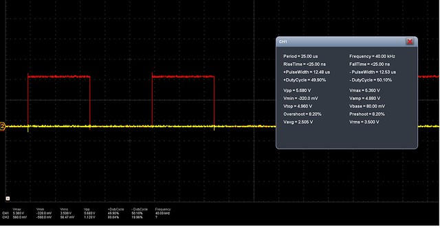
Also for Timer 1 and Timer 2 in in fast pwm mode one of two pins are capable to generate a 50% duty cycle signal with a frequency you can change.
On Timer 1 this pin is pin 9 and on Timer 2 is pin 11.
The program for Timer 1 is:
void setup() {
pinMode(9, OUTPUT);
pinMode(10,OUTPUT);
TCCR1A=0;//reset the register
TCCR1B=0;//reset the register
TCCR1A=0b01010011;// fast pwm mode(WGM10 and WGM11 are 1)
TCCR1B=0b00011001;// no prescaler and WGM12 and WGM13 are 1
OCR1A=199;//control value from the formula
}
void loop() {
// put your main code here, to run repeatedly
}
The program for Timer 2 is:
void setup() {
pinMode(11, OUTPUT);
pinMode(3,OUTPUT);
TCCR2A=0;//reset the register
TCCR2B=0;//reset the register
TCCR2A=0b01010011;// fast pwm mode
TCCR2B=0b00001001;// no prescaler and WGM22 is 1
OCR2A=199;//control value from the formula
}
void loop() {
// put your main code here, to run repeatedly
}
-phase correct pwm
This mode is similar with fast pwm mode but twice slower because it counts on up and after counts on down(see phase correct pwm mode)
The difference is in WGM bits:
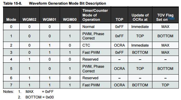
As you can see for fast pwm and frequency controlled by OCR0A mode 7 al WGM bits are 1, but for phase correct also for frequency controlled by the OCR0A WGM01 bit is 0.
Because this timer is twice slower and it increment from 0 to OCR0A and after that, decrement from OCR0A to 0, we must accelarate the toggle of OCR0A and we make this by OCR0A= 100. With OCR0A=100 we have exactly 40kHz and not with 99 like in the previous examples where we aplied the previous formula awith (1+OCR0A) because in this case the frequency is half the result what we obtain from this formula fOCnx=fclk/2*N*TOP, where TOP=OCR0A.
The program for Timer 0 and 40kHz is:
void setup() {
pinMode(5, OUTPUT);
pinMode(6,OUTPUT);
TCCR0A=0;//reset the register
TCCR0B=0;//reset the register
TCCR0A=0b01010001;// phase correct pwm mode(WGM00=1)
TCCR0B=0b00001001;// no prescaler and WGM02 is 1
OCR0A=100;//control value
}
void loop() {
// put your main code here, to run repeatedly
}
Also in this mode only the pins presented in the fast pwm mode are enabled.
For the other two timers things are pretty the same.
-ctc mode
This is the most versatile mode to different frequencies and it uses the formula fOC2A=fclk/2*N(1+OCR2A).
From the above image to put timer 0 in CTC mode we must make the WGM01=1.
For Timer 0 and 40kHz signals on both pins (5 and 6) the program is:
void setup() {
pinMode(5, OUTPUT);
pinMode(6,OUTPUT);
TCCR0A=0;//reset the register
TCCR0B=0;//reset tthe register
TCCR0A=0b01010010;// ctc mode(WGM01=1)
TCCR0B=0b00000001;// no prescaler
OCR0A=199;//control value
}
void loop() {
// put your main code here, to run repeatedly
}
For the other two timers things are pretty the same.


Would there be a way to invert one of the signals? I am attempting to use this code to drive a mosfet for a buck converter and I want to operate in synchronous mode, which requires an inverted pwm signal along with the original running on the same clock cycle so I was wondering if it was possible to modify the code for pin 5 to run the original signal and pin 6 to run the inverted one?
It is possibile but for a 31.372Hz or 62.500Hz(closest for 40kHz).
To generate the signal at 40kHz i have used one pin for timer so…it remain just one for pwm(signal).
The program for what you want at 31.372Hz is:
void setup() {
pinMode(5, OUTPUT);
pinMode(6,OUTPUT);
TCCR0A=0;//reset the register
TCCR0B=0;//reset tthe register
TCCR0A=0b11100001;// phase correct pwm mode pin 6 is in inverted mode first pair “11” and pin 5 in normal mode second pair “10”
TCCR0B=0b00000001;// no prescaler and WGM02 is 0
OCR0A=50;//duty cycle
OCR0B=50;//duty cycle
}
void loop() {
// put your main code here, to run repeatedly
}
The duty cycle is between 0 and 255 with 128=50%.
Signals
In the above link is a picture of these signals, where yellow signal is from pin 5 and the red one from pin 6(inverted).
Hope that help and sorry for late response!
Don’t forget to give us a like!
great article, very close to what im looking for. i need the arduino code that gives 2 pwm signals of duty cycle 70%(adjustable) and a frequency of 35KHz(or close) with a phase difference of 180 degrees(not inverted) . im trying to make a dc dc booster for my inverter
Hi, great article very helpful. Would the program interefere the result if it’s used with PulseIn or micros? Do you have any suggestions to apply this for ultrasonic velocity counting?
First of all micros() work as an interrupt using timer 0. Pulsein also use an interrupt and because is timming for a input pin it will use the timer corresponding to that input(at least in this way i remeber you better check :)) ). My program also make some changes to timers so i won’t recommend you to use all of this functions beacause all of them works on interrupts and i think they would interfere.